-

-

2 h / 100 ft2 for cable installation
4 h / 100 ft2 for electrical installation
CERAMIC SHOWER
You can install a Comfort~One heated floor in a ceramic shower. However, it is important to install a separate cable inside the shower.
STAGE 1
Prepare and check.
Start off on the right foot: prepare the surface to be covered, produce an installation plan, determine the location of the sensor, and then check and record your products’ resistance data.
- Mark the location on the wall where the thermostat will be installed.
- Cut a hole at this location, in anticipation of the installation of a standard electrical connection box 5 cm by 10 cm (2 in. by 4 in.).
- Drill a hole at the base of the wall (at floor level) the size of the protective plate; the cable and the sensor will pass through this hole to reach the thermostat.
 NEW CONSTRUCTION
Before closing the walls, provide for installation of a box 10 cm by 10 cm (4 in. by 4 in.).
However, the wall opening in front of this box will remain 5 cm by 10 cm (2 in. by 4 in.).
On your surface calculation plan, draw the cable installation plan to determine where and how the cables will run.
- 6.35 cm (2.5 in.) from the walls
- 13 to 25 mm (1/2 to 1 in.) from a windowed door, a shower, a bathtub step or a fixed furniture base
- 15 cm (6 in.) from each side of a drain and 30.5 cm (12 in.) from the front and back (toilet, shower)
- 20 cm (8 in.) from a floor-mounted heater
 PRO TIPS

To maintain the minimum distances, draw the contours directly on the floor with a marker.
Mark the location on the floor where the sensor will be installed. It comes out of the hole cut in the base of the wall and must extend 30 to 60 cm (1 to 2 ft) into the heated area of the floor.
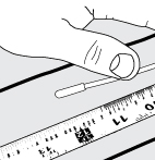
 IMPORTANT
The sensor must be centered between two cables and must not cover ANY heating cable.
 PRO TIPS
The sensor must not be installed in a sunny location, or near an air conditioning system or any heat source (dryer, baseboard heater, refrigerator, etc.) to avoid false readings.
Dig a groove about 6 mm (1/4 in.) deep, near the hole you made in the floor, to insert the non-heating end 3 m (10 ft). It will run inside the wall, between the thermostat and the floor.
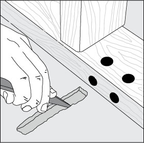
- Ensure that all the nail or screw heads are sunk deeply into the floor. Vacuum the entire surface and then clean thoroughly with a damp cloth.
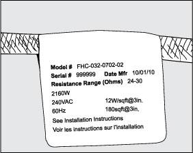
- Take the resistance readings before beginning installation and record the information
- Record the cable serial number, the model number, the voltage and the cable resistance range in your Sensor and Cable Resistance Log (page 6 of the Installation Guide). If you install more than one cable, take this step for each of them. If the results differ, contact your dealer.
- Compare the results obtained with the figures indicated on the cable label.
- Wind the identification label of the non-heating cable around it. Fasten it in place with a piece of electrical tape. DO NOT REMOVE THE IDENTIFICATION LABEL.
 PROTIP
Use a quality digital ohmmeter, which can measure up to 20,000 ohms (Ω), to take these readings. Analog meters (with a moving needle) are not accurate enough for these products. They must not be used.
STAGE 2
Proceed with the electrical installation.
Electrical installation is a special stage. It is the only stage that requires that certain tasks be performed by a certified professional. If you are not qualified to perform electrical work, entrust this stage to an electrician who has received the necessary training.
- Install a 120 VAC unipolar circuit-breaker for a 120 VAC system.
- Install a 240 VAC bipolar circuit-breaker for a 240 VAC system.
Have an electrician install one or more circuit-breakers with a maximum of 20 A in the breaker panel, depending on the system load.
- Run the circuit-breaker cable to the control box. Leave about 15.2 to 20.3 cm (6 to 8 in.) of extra cable outside the box. Use a 14 or 12-gauge type NM cable or another accepted electrical cable to connect the junction box to the control box.
- Drill 2 holes 1.27 cm (1/2 in.) in diameter in the base plate directly below the electrical control box.
- Then drill two horizontal holes intersecting as closely as possible with the upper holes in the surface of the floor.
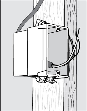

 New construction
Cut a length of electrical conduit 1.27 to 1.9 cm (1/2 to 3/4 in.) in diameter to run from the control box to the base plate. Mark “Floor/bathtub heating” or any similar description next to the corresponding circuit-breaker in the panel supplying power to the system.
 Existing construction
Cut a piece 5 cm by 5 cm (2 in. by 2 in.) wide in the surface of the wall at floor level, below the control box. Mark “Floor/bathtub heating” or any similar description next to the corresponding circuit-breaker in the panel supplying power to the system.

- If you are installing one or two cables, use an extra-deep single box to have enough room for cabling.
- If you are installing 3 cables, use a 10 cm (4 in.) square box.
- If you are installing more than three cables, connect the conductor wires in a junction box and then route the power supply to the control box.
- Use a standard junction box with a cover.
- Mount it underneath the floor, in the attic or in another easily accessible location. It must be fairly easy to access. It must not be installed behind a wall, a cabinet or any similar obstruction.
- Then use 14 or 12-gauge type NM cable or another accepted electrical cable to connect the junction box to the control box.
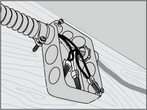
 IMPORTANT
New Construction
Follow the rules prescribed in the U.S. National Electrical Code (NEC) and the Canadian Electrical Code (CEC) and the other local electrical code requirements in installing this system.
Existing Construction
We recommend installing the system on a separate circuit running directly from the breaker panel. In existing construction, it may be difficult to do this, depending on the location of the cable and the breaker panel. We then recommend that you use an existing circuit, but only if the load capacity is sufficient to accept both the system and any other loads applied on the circuit.
STAGE 3
Install the cable
Follow your installation plan. Proceed section by section. Cut and glue or staple your templates. Install your cables.
- Use the sketch and draw lines on the floor to indicate where to install the templates and the cables.
- Decide the direction of the cables on the floor for the easiest coverage.
- Install the template about 6.35 cm (2.5 in.) from the wall. For the counter or vanity setbacks, install the template so that the cable is about 3.8 to 5 cm (1 1/2 to 2 in.) from the counter or vanity.
- Cut the template according to the length of the first surface to be covered.
- Install the template on the floor with a hot glue gun or staples.
- Cut another template piece for the other end of the surface and fasten it 6.35 cm (2.5 in.) from the wall or walls or any other obstructions.
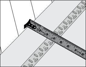
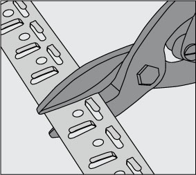
WARNING:
- NEVER cut or superimpose the cable!
- NEVER space the heating cables less than 6.35 cm (2.5 in.) apart.
- NEVER install a heating cable less than 15 cm (6 in.) from each side of wax bowl rings and from each side of the plumbing and less than 30.5 cm (12 in.) from the front and back of the bowl.
- NEVER install the heating cable under cabinets, sanitary facilities or walls.
 PRO TIPS
- Depending on the shape of the surface to be covered, you may have to consider how to cover several small surfaces.
- In the case of an irregularly shaped room, you will have to install the templates so that they hug the contours of the room.
- Unwind the cable as far as the factory splice.
- Leave the cable reel on the floor.
- Glue the factory splice to the floor with the hot glue gun.
- Fill the first cable section before installing other templates.
- Brand the cable from front to back on the surface.
- Inspect the work.
- Check the spacing.
- Check that no cable overlaps.
- Check that no cable is damaged.
- Check that all the places to be heated are covered with the cable.
- Take cable resistance readings.
- Record these readings in the Sensor and Cable Resistance Log.
- Place cardboard or carpeting on the cables to protect them from any damage until installation of the floor covering.
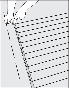
IMPORTANT RULES :
- Always embed the factory splices and all the heating cables completely in the mortar.
- NEVER slide the conductor wires through the heating cables, under the baseboards or in any other places where they could be damaged.
- NEVER join two cables in series.
- NEVER bend the factory splices.
 PRO TIPS
If there are other places to cover with cable, cut the necessary template lengths, fasten them to the floor and start braiding the cable at this location. To fasten long lengths of heating cable, place several template lengths at intervals of 0.9 to 1.2 m (3 to 4 ft).

-
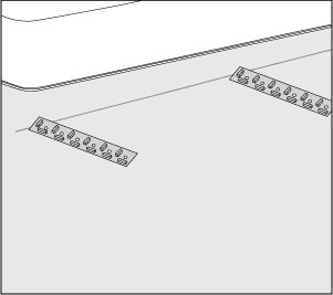
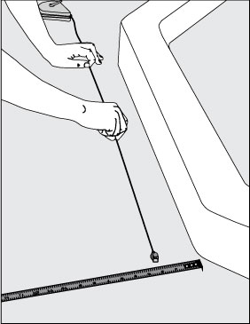
 Corner shower or vanity (angular location)
- Cut several template pieces a little longer than the cable spacing used.
- Mark the floor 6.35 cm (2.5 in.) from the angle.
- Use a tracing cord to fasten each template piece to the floor.
- Make sure to space the cables uniformly in relation to each other.
- Fill this section with the cable.
 Doorway
- Cut two template lengths so that they are a little shorter than the doorway opening.
- Then fasten the two templates parallel to each other.
- Fill this section with the cable.
 Banquettes or steps
- Place a single run ascending the riser.
- Use the templates to fasten the cable to the seat according to the desired spacing.
- Install a single run descending the riser.
- If necessary, use hot glue to fasten the cable flat against the riser. The cable of the riser and the seat MUST be completely embedded in the mortar. It must be located under an approved floor covering.
- Encadré et espacé
- Le câble de la contremarche et du siège DOIT être entièrement encastré dans le mortier. Il doit se trouver sous un revêtement de plancher approuvé.
 Shower space
It is important to install a separate cable inside the shower.
- Cut the template lengths and fasten them with the hot glue. DO NOT USE FASTENERS THAT PENETRATE THE WATERPROOFING MEMBRANE OR THE WATERPROOFING SYSTEM.
- Fill the floor space with the cable, leaving a space of at least 5 cm (2 in.) from the edge of the flange around the drain.
WARNING :
- Ensure that the factory splice of the conductor wire (the connection between the conductor wires and the heating cable) is located outside the shower space and at least 2.54 cm (1 in.) from the showering openings and other sensitive locations normally exposed to water.
- Ensure that the control is located at least 1.2 m (4 ft) from the shower openings so that it is not exposed to water or touched by a person in the shower.
- Ensure that the cable is not placed where the door hardware, the support bars or other articles could be mounted on the floor.
 Shower bench
- Cut the template lengths and fasten them to the upper surface of the seat with hot glue. DO NOT USE FASTENERS THAT PENETRATE THE WATERPROOFING MEMBRANE OR THE WATERPROOFING SYSTEM.
- Use hot glue to fasten a cable length along the side of the bench riser.
- Fill the seat space with the cable.
-
Chisel a groove in the floor to place the factory splice of the conductor wire.

- Pull the conductor wires to the electrical control box.
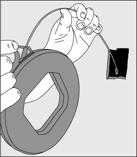
- Fasten the conductor wire splice in the chiseled grooves with hot glue.

- At a distance of about 0.6 m (2 ft) under the control, chisel a groove for the sensor. Ensure that the sensor is placed between two heating cables.
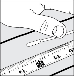
- Glue the end of the sensor in the groove with hot glue.
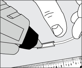
- Pull the sensor wire to the electrical control box.
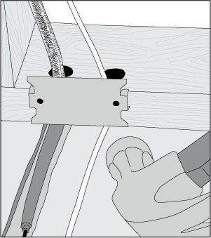
- Fasten a plate over the wires with steel nails to protect them.
WARNING
The conductor wire splice MUST BE COMPLETELY EMBEDDED in the mortar bed. NEVER bend the factory splices.


